How to Draw BPMN 2.0 Business Process Diagram?
Business Process Modeling Notation 2.0 makes a great improvement in business process modeling. There are number of new notations introduced in BPMN 2.0. In this tutorial, we will show you how to draw choreography task and message. We will draw the example diagram of BPMN 2.0 draft specification (An example of stand-alone Choreography diagram). By finishing this tutorial, you will be able to draw a business process diagram that looks like this: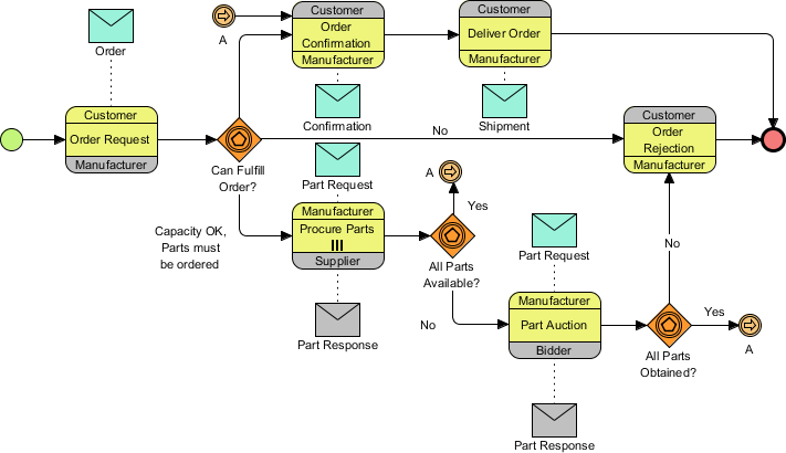
Drawing a BPMN 2.0 Business Process Diagram
- Create a new project by selecting Project > New from the application toolbar. In the New Project window, enter Tutorial as the project name and click Create Blank Project.
- Let's create a model first. Select View > Project Browser from the application toolbar.

- Open the Model Structure page in the Project Browser.

- Click the New Model button at the top of the model list on the left-hand side.

- Name the model Sales and click OK to confirm.

- You can create pools directly under the Sales model without using a diagram. Let's try it. Right-click on the Sales model and select Model Element > New Model Element... from the popup menu.

- You can search for the model you want to create in the New Model Element window. Enter Po in the Model element type text field to search for Pool.

- Enter Customer as the Model element name.

- Uncheck Open specification after create and click OK to continue.
- Repeat these steps to create the pools Bidder, Manufacturer, and Supplier.
- Right-click on the Sales model and select Sub Diagrams > New Diagram... from the popup menu.

- In the New Diagram window, select Business Process Diagram and click Next. Keep the diagram name as provided and click OK to create the diagram.

- You can now start creating the business process diagram. First, let's create a start event. Select the Start Event tool from the diagram toolbar and click on the empty area of the business process diagram.

- Now, click on the start event and drag out the Resource Catalog icon.

- Release the mouse button on the blank area of the diagram and select Choreography Task from the Resource Catalog.

- Enter Order Request as the name of the choreography task and press Enter to confirm.

- Right-click on Order Request and select Open Specification....

- Select the Customer pool as Participant 1.

- Select the Manufacturer pool as Participant 2.
- Select the Customer pool as the Initiating participant.

- Click OK to confirm. The Order Request task is now done. You can see that the initiating participant is shown in the same color as the task, while the non-initiating participant is shown in gray.

- Let's create a message between Customer and Manufacturer. Click on the Order Request task and drag out the Resource Catalog icon.

- Release the mouse button above the choreography task and select Message from the Resource Catalog.

- Then, select New Message Flow from "Customer" to "Manufacturer" from the popup menu.

- Enter Order as the name of the message and press Enter to confirm.

- Create an Event-based Exclusive Gateway from Order Request. Again, click on Order Request and drag out the Resource Catalog icon. Release the mouse button in the empty space of the diagram and select Gateway from the Resource Catalog to create a gateway.

- Enter Can Fulfill Order? as the name of the gateway and press Enter to confirm. You can insert a line break by pressing Alt + Enter.

- Right-click on the gateway and select Type > Event-Based Exclusive Decision/Merge (XOR).

- Repeat the steps to complete the business process diagram, like this:

- There could be multiple instances of the 'Procure Parts' activity running simultaneously. Let's represent this by setting the loop type of the Procure Parts task to Multi-Instance Loop. Right-click on the Procure Parts task and select Open specification... from the popup menu.
- Select Multi-Instance Loop for the Loop type combo box.

- Click OK to confirm. The Multi-Instance loop marker is now shown in the Procure Parts task.

- Let's create messages between Manufacturer and Bidder on the Part Auction task. Using the Resource Catalog, create a Message from the Part Auction activity. Select New Message Flow from "Manufacturer" to "Bidder" from the popup menu.

- Name the message Part Request.
- Repeat the step to create another message to the Part Auction task. This time, select New Message Flow from "Bidder" to "Manufacturer" during creation. Name the message Part Response. You can see that the message from Bidder to Manufacturer is in a different color because Bidder is a non-initiating participant.

- The gateways All Parts Available? and All Parts Obtained? in the business process diagram only model the "false" situation. What about the "true" case? Assuming that the flow should go back to the Order Confirmation task, we don't want to make the diagram too complicated with too many connector lines. Let's represent the flow using a pair of intermediate events. Click on the All Parts Available? gateway and drag out the Resource Catalog icon. Release the mouse button above the gateway and select Intermediate Event from the Resource Catalog. Enter A as the name and press Enter.

- Name the connector Yes.
- Right-click on the intermediate event and select Trigger > Link Trigger.
- Repeat the steps to create another link event from the All Parts Obtained? gateway.

- Select Link Intermediate Event from the diagram toolbar.

- Click on the left-hand side of the Order Confirmation task and name it A. Connect it to the task. Your diagram should now look like this:

- Create the other messages. Finally, your business process diagram should look like this: