How to Use Sub-Diagrams?
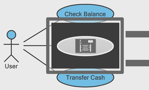
A clear and understandable model never includes everything in a single diagram. Instead, ideas are divided into multiple layers which commonly known as the abstraction layers. Take use case as an example. A simple ellipse shape cannot represents every details related to a use case. Such as you cannot see how users interact with the target system and the underlying business logic through ellipse. Therefore, you have to use a separate diagram to elaborate those details.
However, creating separate diagrams leads to the problem of project organization, i.e., how you can keep the model element and its associated diagrams together. In Visual Paradigm, you can achieve this by using sub-diagrams. In this tutorial, you will learn how to elaborate the details of a model element by using sub-diagrams, how to navigate between parent models and sub-diagrams, and also some typical usages of sub-diagrams.
Creating a Sub-Diagram
A sub-diagram can be created easily via the resource-centric interface. To create a sub-diagram:
- Click on the model element to bring up the resource-centric interface.
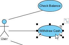
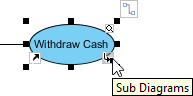
- Click on the Sub Diagrams resource icon at the bottom right corner of the model element.
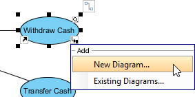
- Select New Diagram... from the popup menu.
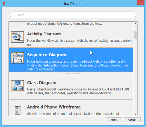
- Select the type of diagram that you would like to create and click Next. Specify its name and description (optional) and click OK.
- Click OK to confirm. Now, a brand new diagram is created as the sub-diagram of your selected model element.
Add an Existing Diagram as a Sub-Diagram
Besides creating a new diagram as a sub-diagram, you can also use an existing diagram as a sub-diagram.
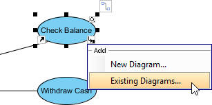
- Click on the Sub Diagrams resource icon again. But this time select Existing Diagrams...
- Choose the target diagram(s) in the Add Sub Diagrams window.
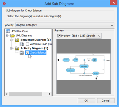
- You can browse the diagram based on the diagram category or based on the model hierarchy.
- Once you have picked the diagram, then press OK to confirm. After that, the selected diagram(s) will become sub-diagram(s) of your selected model element.
Navigation Between a Model Element and Its Sub-Diagrams
You can easily navigate between a model element and its sub-diagrams. To do this:
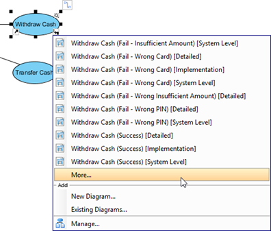
- Click on the Sub Diagrams resource icon.
- Select the target diagram from the popup menu. A preview of the target diagram will be shown next to the popup menu.
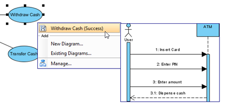
- Click on the target diagram to jump into it.
If the model element has a large number of sub-diagrams:
- Select More... from the popup menu.
- Select to bring up the Open Sub Diagram pane.
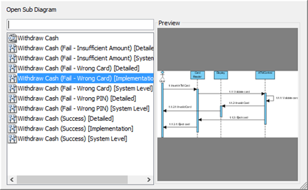
- Select the diagram from the list. You can use the filter to find the diagram you need.

- Double-click on the diagram name to open it.
From the sub-diagram, you can navigate back to the parent model element by clicking on the link in the breadcrumb on top of the diagram.
Knowing Which Model Element Has Sub-Diagram(s)
You can easily remember which element possesses sub-diagram(s) when your project size is simple and small. However, when it becomes larger, it will become a difficult task to walk through each model element to see whether it contains sub-diagrams or not. To overcome this problem, you can turn on the Model Indicator by selecting View > Model Indicator from the application toolbar.
By turning on the Model Indicator, the sub-diagram resource icons will be shown as long as the model element contains sub-diagram(s) even if you are not selecting it. This helps you to identify the model element which has sub-diagram(s).

Sub-Diagram and Model Structure
When creating a sub-diagram or associating an existing diagram as a sub-diagram, the diagram itself and its containing Master View elements will become the children of the selected model element. Thus, the model structure would be changed when you create sub-diagrams.
Typical Usage of a Sub-Diagram
The major usage of a sub-diagram is to elaborate the details of a particular element. Below are some typical usages where sub-diagrams are helpful.
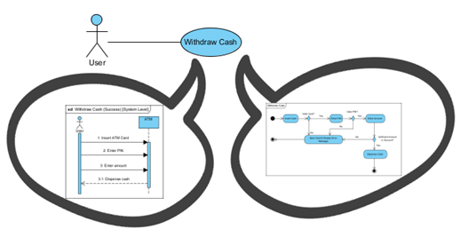
Elaborate a Use Case Using UML Activity Diagram and Sequence Diagram
A use case is used to model the goal which a user wants to achieve when using the system. However, a use case itself does not involve any detail about how to achieve this goal. Instead, it contains various scenarios, and each scenario becomes a possible execution path in the system.
In order to model the detailed interactions between users and the system or even between different models of the system in each execution path, we can use a UML Sequence Diagram. Furthermore, we can also use an Activity Diagram to model the overall flow logic of the use case.
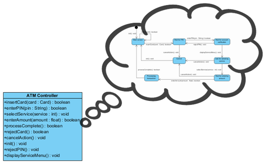
Elaborate the Internal Stage Change of a Class
While classes are the basic construct for building a a system, a class model focuses on the static structure of the system. We can make use of the State Machine Diagram to model the internal state change of a class against external events at runtime. This helps us to understand the dynamic behavior of a class.
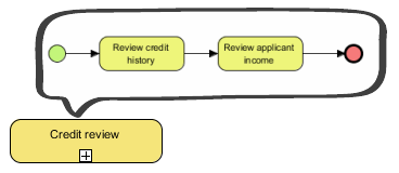
Elaborate BPMN Activity with a Sub-Process Diagram
The sub-process in a standard BPMN notation provides abstraction for internal details by creating sub-process diagram(s) for elaboration.
Watch This Tutorial on YouTube
Here is the video version of this tutorial.