How to Find Use Cases from Business Process (BPMN)?
The BPMN is being increasingly used for identifying requirements for software that supports business processes. Software requirement is often found to be misaligned with business processes. Therefore, requirements elicitation based on business process models would assure the alignment between business process and software models and thus, likely to deliver what users expected.
Development teams can use business process models to visually document business workflows and associate use cases with those business processes for modeling the desired features to be achieved by the system. In this tutorial, we will explain in detail how to use the Model Transitor function to establish traceability between use cases and business processes.
What are BPMN and BPD?
BPMN provides business analysts with a set of graphical notations for modeling business processes. It was initially developed by the Business Process Management Initiative (BPMI) and is now maintained by the Object Management Group (OMG). One of the motivations for developing BPMN is to provide a common graphical language for people in different roles, from different countries, and/or with different spoken languages to understand the same business process without barriers.
BPD, short for Business Process Diagram, is where a business process is modeled using BPMN. It is a flowchart-like diagram that depicts the process flow, participants involved, and message exchanges between participants. Business analysts draw BPD(s) to model how different participants collaborate to accomplish a business objective. After validating the completed business model against the end-users, a system analyst can then start planning the system.
The following is a simple BPD of a registration process for an organization. It covers most of the typical modeling notations you would see. Let's take a look.
| Notation | Description |
|---|---|
 |
Pool - Represents a participant within a process. In BPMN, both pools and lanes are used to represent participants. A lane is contained within a pool for modeling a sub-partition of the parent pool. |
 |
Start event - The beginning of a process. Triggers can be defined to tell readers in what situation the process will be triggered. For example, when an Email is received, when it is Monday morning, or when an error has occurred. |
 |
Task - An atomic activity that designated participants (modeled by pool/lane) might perform. Tasks and other flow objects are connected to form a complete business workflow. |
 |
End event - The end of a process. A result can be defined to tell readers what will happen when the process ends. For example, to issue a signal, or to produce an error. |
In this tutorial, we are not going to focus heavily on BPDs or business process modeling. If you want to learn more about BPMN, BPDs, or business process modeling, please read the tutorial Introduction to BPMN Part I to IV.
What is a Use Case Diagram?
Use case modeling refers to the technique of capturing high-level user requirements using a UML use case diagram. A use case model is designed for software or system designers, not for business people.

There are three main elements in a use case diagram.
| Notation | Description |
|---|---|
 |
Use case - Each use case represents a user goal, which is an objective the user of the system wants to achieve. Note that use cases can only be used to show what the user wants to do instead of what the developer needs to develop, although they may be the same in some cases. If you want to document or model the functions involved in a use case, you may use the flow of events tool, or to elaborate a use case with a sequence diagram/activity diagram. Just keep in mind that use case modeling aims at modeling what the user wants to achieve. |
 |
Actor - A user of the system. The word 'user' here is not limited to humans. It can be a system that interacts with our system to fulfill a certain business objective. |
 |
Communication link/Association - Connects an actor and a use case to indicate the access of the system by the actor. Each communication link implies a sequence of transactions between the actor and the system. |
Transition from BPD to Use Case Diagram
Although BPDs and use case diagrams should not necessarily rely on each other, they can be related in a complementary manner. Usually, we develop software to automate or optimize certain workflows of business processes. With a BPD, you can understand how participants work together and who is responsible for what, which helps us identify what functions they need the system to support. Those system functions (workflow or business process) that a user wants can be modeled with use cases and subsequently developed by the team. As a result, we can say that a BPD helps you identify use cases for a system under development.
Visual Paradigm is a visual modeling tool that supports transitioning from business process modeling to use case modeling (from business requirements to application requirements) by establishing traceability linkages between the two models through its model transitor feature. We need this traceability for the following reasons:
- We can ensure the system fits into real-world usage by studying the part of the process flow a use case involves.
- To answer questions like "Why do we need this (system) function?" by tracing the part of the process from which a use case transitioned.
- To answer questions like "Has a specific operation been implemented already?" by tracing from the BPD to the use case diagram.
BPD vs. Use Case Diagram
Some people may think that a use case diagram is similar to a BPD, but they are quite different in notations and purposes. Remember that BPMN is designed for business people, while a use case diagram is for system analysts or system developers. They serve different purposes and view a business from two distinct perspectives. That's why in the previous section I summarized the relationship between a BPD and a use case diagram by saying "a BPD helps you identify use cases." A BPD can only give you hints when identifying use cases. There is no rule stating that every task existing in a BPD is equivalent to a use case. However, we could elaborate on a business process using a use case for the automation of a feature by the target system.
In the case study, I will give you some ideas about what you should pay attention to when transitioning a BPD to a use case diagram. You will then understand how different they are.
Case Study: The True Aqua Distilled Water Company
The True Aqua Distilled Water Company is a young distilled water supplier in the city. They sell distilled water for business and home use. The following is a textual description of their water delivery process.
|
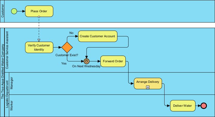
To order distilled water, customers either call the ordering hotline or send us an Email. Currently, 90% of the orders come from phone calls, while 10% are placed by Email. The customer service assistant who receives the order will check whether the customer is an existing customer or a new one. If the customer has never ordered before, the customer service assistant will create a customer account for them before proceeding to water delivery. The delivery of distilled water is carried out once a week on every Wednesday. So on every Wednesday morning, the customer service assistant will forward orders to the Logistics Department for delivery. Once the manager in the Logistics Department has received the orders, he will arrange the delivery by assigning workers for different orders, printing and posting the schedule. The workers receive the calls and deliver water to the customer accordingly. |
A business process model has been created based on the description. Now, you are requested to develop a computer system to optimize the whole process. The first thing you need to do is to develop a use case model. With the help of the BPD, try to develop a use case diagram.
- Download Distilled Water Delivery.vpp. You can also find this file at the bottom of this tutorial.
- Open the downloaded .vpp file in Visual Paradigm. To open a project, select Project > Open from the application toolbar.
- Open the BPD Distilled Water Ordering Process. Study the process flow carefully.

- The process starts when a customer places an order. Here we can think of a use case - Place Order. The use case will help automate the process by providing an interface for the customer to place an order without the assistance of a customer service assistant, help verify customer identity, and create an account if the customer does not exist. Right-click on Place Order and select Related Elements > Transit to New Use Case... from the popup menu.

- This prompts the Transit Model Element window, where you can select the model to place the use case and actor, and rename them. In this case, we are pleased with the names of the use case and the actor. Let's keep them unchanged. Click OK.

This forms a new use case diagram in UeXceler.
- Go back to the BPD.
- Let's consider the task Create Customer Account. In the business process, the customer service assistant needs to create an account for every new customer. In the new system, this can either be a part of the Place Order use case, or be a separate use case triggered by the customer service assistant manually. In a real-world situation, you should clarify this kind of doubt with the stakeholder because an incorrect use case model will lead to the development of functions that do not match user's expectations. In this example, let's assume that the user wants the Create Customer Account task to be a task done by the customer service assistant. Let's create a use case from it. Right-click on Create Customer Account and select Related Elements > Transit to New Use Case... from the popup menu.

- Again, we are pleased with the name of the use case and actor. Keep everything in the Transit Model Element window unchanged. Click OK. The use case diagram is updated with a new use case and actor. Let's take a look.

- Go back to the BPD. Let's move on to the sub-process Arrange Delivery. The manager of the Logistics Department can use the system to perform scheduling and notify workers to deliver water. Therefore, this is also a use case of the system. Right-click on the sub-process Arrange Delivery and select Related Elements > Transit to New Use Case... from the popup menu.
- Check the actor "Manager" in the Transit Model Element window. If we keep the name of the actor as Manager, this is ambiguous in the use case model because there may be many departments with many different managers in the company. Therefore, rename the actor to Logistic Department Manager.

- Click OK. The use case diagram is updated.

- Go back to the BPD. The final task Deliver Water is a job that can only be done by a human and has nothing to do with the system's interaction. Therefore, we do not need to create a use case for it.
- Suppose the regional manager wants the system to support a new function that can generate a report to show statistics on orders. This function can help him review and refine the marketing strategy. Although this function had not been modeled in the business process model, we can draw it directly in the use case diagram. Open the use case diagram. Draw an actor Regional Manager. Create a use case Generate Statistic Report from it with an association in between.

- Let's say the client wants to allow the customer to view billing statements and to cancel orders. Besides, the client wants to allow the logistic department manager to print a logistic report. Draw the use cases respectively.

- Tidy up the diagram.

- The transition relationship enables you to trace the business process model from the use case model (and vice versa). Let's try. Place the mouse pointer over the Place Order use case.

-
Click on the Model Transitor resource at the bottom right corner of the shape. Select Transit From > Distilled Water Ordering Process<.Place Order from the popup menu.

This opens the BPD with the task Place Order selected.